
AUTOMATIC MACHINES AND WORKING FINISHING LINES
FOR PROFILES WOOD-MDF-PVC-POLYSTYRENE


![]()


![]()
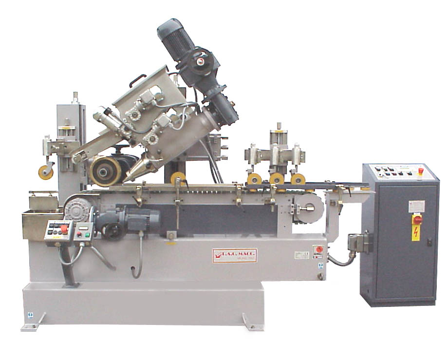
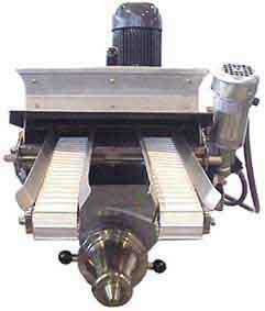
AUTOMATIC COMPO MACHINE - PM/L MODEL
GOVERNED BY SPEED-VARIATORS
AUTOMATIC COMPO MACHINE - PML/S MODEL
GOVERNED BY INVERTERS
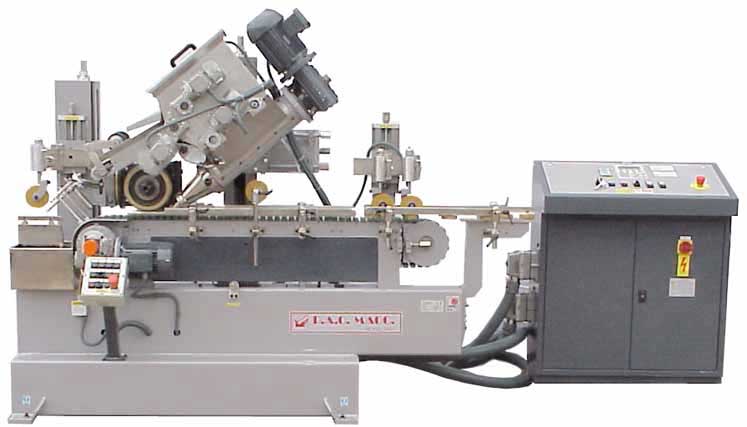
GENERAL DESCRIPTIONS OF THE MACHINE
The machine is built with a solid structure of steel plate and tubular elements, electrically welded together to provide a high degree of solidity and stability. The machine has a conveyor system, with a twin 5/8 chain 110 mm wide covered with para rubber. The conveyor is driven by a motor and gearbox to provide different speeds suitable for any type of work. The sliding columns are positioned to the side of the conveyor unit. The columns support the operating heads, the vertical and horizontal slides as well as the inclined accurately with just one handle.
DESCRIPTIONS OF THE OPERATING UNITS
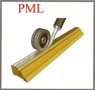
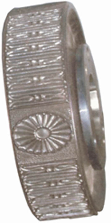
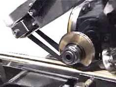
- EMBOSSING UNIT
The embossing head can produce ornaments in any type of relief by adding wood pulp. The cylinder is mounted on the shaft of a speed motor with Inverter so that the rate of rotation can be modified according to the diameter and feed rate. ( Any Cylinder Diameter can be used ) - It is also possible to use a second idle sleeve (with bearings) on the shaft . The unit which holds the cylinder can be tilted through 90° (45° to the right and 45° to the left ) to the conveying plane.
- WORM-SCREW UNIT
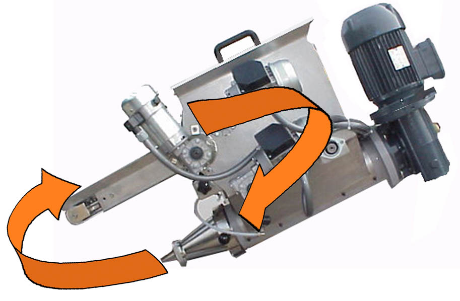
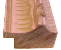
The wood pulp is fed by a worm-screw driven by a motor governed by Inverter (PML/S MODEL )(OR SPEED-VARIATOR ON PM/L MODEL ) and it is forced through an interchangeable end nozzle of varying sizes. By altering the rate of rotation of the worm-screw the correct quantity of pulp is obtained according to the size of the ornament and to the feed rate. The circular pulp extrusion is deposited on the moulding and immediately compressed by a negative pressing cylinder with various diameters and shapes. The assembly can be tilted (in two directions).
- SIDE GUIDE UNIT
The side guides maintain the profile aligned (by means of rods marked off in millimetres) with the conveyor and support the excess wood-pulp, at the edges of the pressing cylinder, which the operator has to remove by hand. The surplus is recovered in the final tray and all of it is returned onto the feed belt for reuse.
- WOOD-PULP FEED CONTAINER UNIT
The unit is equipped with a 29 Kg. wood pulp container. The operator places complete wood-pulp drums into the container. The structure supporting the belt is fully enclosed and prevents any accidental contact on the part of the operator with the worm-screw. The protective screens are fastened with bolts; the cover touch a safety micro switch and isn't possible to work without. In any case it is possible to feed the container also when the machine is working with out stop production. The wood pulp excess is rewind immediately by two ant solvent belts: the speed is electronically synchronized with the working speed.
TECHNICAL DETAILS:
LENGTH 1.700 mm.
WIDTH 1.100 mm.
HEIGHT 1.800 mm.
WEIGHT 1.145 KG.
Installed power kW. 6
Working speed 8 - 40 MT/min.
Embossing shaft diameter D. 40 mm.
Embossing roller diameter D.200 mm.
Worm screw power kW. 1.8
Conveyor motor power kW. 0.75
Embossing roller power kW. 1.1
Compressed air pressure 3 Bar
Air requirements 40 nl/min SCFM 1.4


ASK FOR OUR COMPLETE CD MULTIMEDIA PRESENTATION
Copyright(c) 2009 - paomacc
group -
info@paomacc.net